SolidWorks
FEA
GRBL Firmware
Stepper Motors
Lead Screws
Linear Bearings
3D Printing
Machine Design
Overview
A Three-Axis Mill — Built From Scratch
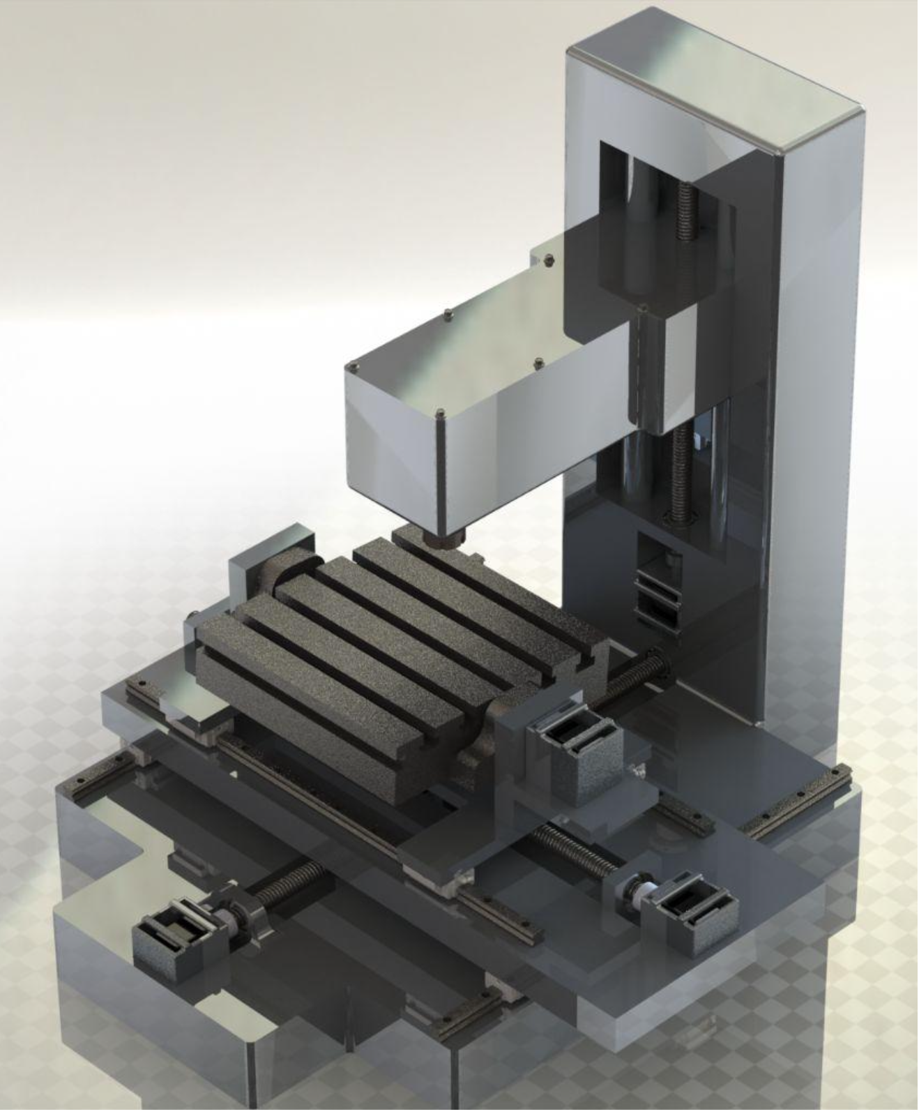
A three-axis CNC milling machine designed to reliably and accurately machine lightweight
materials — foam and wood — within practical fabrication constraints. Every component
was designed in SolidWorks, validated with FEA, and assembled by hand.
Engineering Challenges
- Structural rigidity under cutting loads
- Minimizing deflection across the gantry span
- Achieving smooth, backlash-free linear motion
- Mitigating vibration and mechanical misalignment
Design Approaches
- CAD modelling in SolidWorks
- FEA deformation analysis under load cases
- Strategic linear rail and lead screw positioning
- 3D-printed modular components with adjustable fastening
Linear Guidance
Supported linear rails + linear bearings
Drive Mechanism
Lead screws with anti-backlash nuts
Actuation
NEMA stepper motors
Controller Firmware
GRBL (open-source G-code interpreter)
Modular Parts
3D-printed with adjustable fastening
Target Materials
Foam & wood
Key Contributions & Outcomes
- Modelled the full assembly in SolidWorks — frame, gantry, spindle mount, motor mounts, and cable management
- Ran FEA deformation analysis to validate gantry stiffness and minimize deflection under cutting loads
- Selected and positioned linear rails and lead screws to balance rigidity, travel range, and cost
- Designed and 3D-printed modular component mounts with adjustable fastening for easy alignment correction
- Configured and tuned GRBL firmware — steps/mm calibration, acceleration limits, homing routines
- Achieved controlled three-axis motion with low deflection and acceptable machining accuracy for foam-based materials
- Demonstrated reliable toolpath execution with good repeatability across multiple test runs
Technical Approach
FEA-Informed Structural Design
Supported linear rails were chosen over unsupported rod guides to minimize gantry flex
under cutting loads. FEA in SolidWorks Simulation applied representative cutting forces
as distributed loads along the gantry beam, identifying the critical deflection points.
Rail span and bearing carriage count were adjusted until deflection fell within acceptable
tolerance for the target materials.
GRBL firmware interprets G-code commands from CAM software and drives the
stepper motor controllers. Steps-per-mm calibration was performed by measuring actual travel
against commanded distance and iterating the GRBL configuration until dimensional accuracy
was achieved. Acceleration ramp profiles were tuned to prevent step loss during direction
reversals without sacrificing cycle time.